Magnetic Levitation
Levitation
- Introduction
- Why
- Other Maglev
- Hard Drive Maglev
- Schematic
- Parts List
- Buying Parts
- Woodworking
- Other's
- Photographs
- Infrared Emitter
- Photodetector
- Reference Det
- Difference Amp
- Feedback Loop
- Loop Equations
- Bode Plot
- Phase Lead
- Output Amp
- Coil Driver
- PWM
- Lifting Coil
- PSPICE
- Build Time
- PCB
- Power Supplies
- Setup
- Test Power
- Test IR Emitter
- Test Signal Det
- Test Ref Det
- Adjust Sensing Res
- Test Diff Amp
- Test Non-Invert Amp
- Test Coil Driver
- Test Lifting Coil
- Results
Levitator Photographs
What does it look like? How are the parts arranged on the breadboard? Are you actually going to build one of these? You are going to need close-up photos.
Breadboard Layout
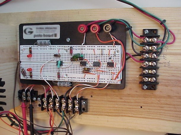
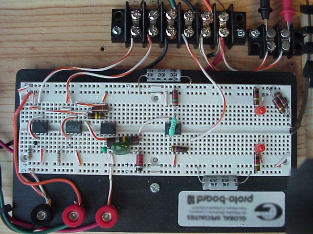
The electronics are mounted in a push-down breadboard. These breadboards are available from Radio Shack ($22) and from most other stores that sell electronic components. Prices range from $5 and up, depending on size and whether it has those nice little binding posts.
 Each
component is labelled in the image at left. (Click on the image for the full size picture.) The
stages are laid but left-to-right in the same order as the schematic. This is a top view; the
front of levitator is at the bottom of the photo.
Each
component is labelled in the image at left. (Click on the image for the full size picture.) The
stages are laid but left-to-right in the same order as the schematic. This is a top view; the
front of levitator is at the bottom of the photo.
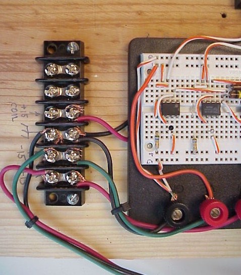
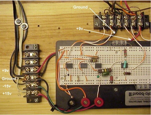
The connectors are also shown in the photo. At the top right is a two-terminal strip which is only used to connect the leads to the little voltmeter permanently mounted on the levitator. At the top middle is a six-terminal strip for connections to the coil and opto-detectors and 2N3055 transistor driver. At the bottom left are three binding posts for the +/- 15vdc power connections.
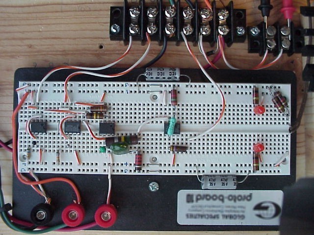
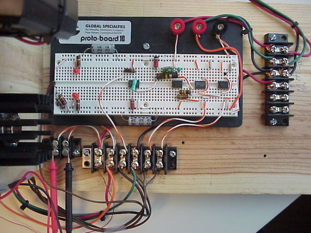
Below are a variety of images to provide slightly different views of the parts layout. Hopefully
you can make out anything that might not be clear in the labelled image above.
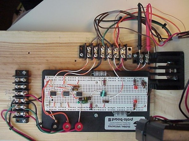
Lifting Coil Area
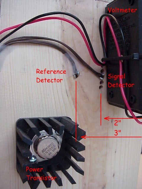
Some important parts are mounted in the area around the lifting coil. The 2N3055 power output transistor is on the left, mounted in a spiky heat sink. An inexpensive voltmeter is held in place with tie-wraps, just above the power transistor. The infrared emitter is on the right, and the two opto-detectors are on the left of the coil behind the voltmeter.


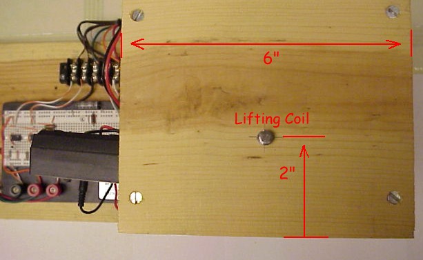

The lifting coil has two wires coming out. You can see a thin magnet wire and a thicker orange wire. The orange wire is nothing special. I had a little ooopsie when I built the coil, because one of the magnet wires broke off when I took the coil from my coil-winding form. So I soldered that big orange stranded hookup wire to it and covered the solder joint with heat-shriek tubing.
Inside the box in the back left you can see the wires to the power transistor. To help tell them apart, I used different colors for each connection. Green is for emitter, Black is for base, and Red is for collector. The red wire (collector) is soldered to a lug under a mounting screw, because the entire case around this transistor is connected to its collector. The green and black wires disappear into holes in the wood, because the transistor's pins are not as long as the wood is thick. Suggestion: Use thinner wood than I did!
Infrared Emitter and Detectors
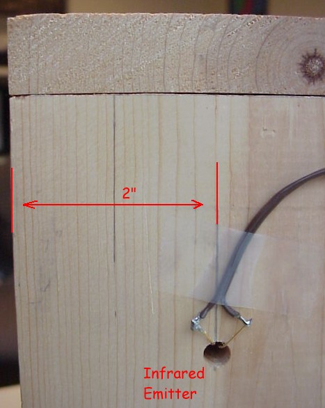 These
photos show the high-tech and expensive mounting brackets for the emitter and two detectors.
Through a (not very) complicated design process, I found the size of hole needed to loosely hold
the parts in wood. The parts are pressed into place, and the leads soldered to two-conductor
wire. This wire is just a handy 24-gauge zip wire, like a lamp cord wire only smaller. Any kind
of wire will work, but two-conductor wire makes a neater presentation. The wires are anchored
in place with a single-dimensional bonding element (transparent tape).
These
photos show the high-tech and expensive mounting brackets for the emitter and two detectors.
Through a (not very) complicated design process, I found the size of hole needed to loosely hold
the parts in wood. The parts are pressed into place, and the leads soldered to two-conductor
wire. This wire is just a handy 24-gauge zip wire, like a lamp cord wire only smaller. Any kind
of wire will work, but two-conductor wire makes a neater presentation. The wires are anchored
in place with a single-dimensional bonding element (transparent tape).
The reference detector is in the single hole on the left. The signal detector is in the middle of a column of holes on the right. The column of holes makes it possible to adjust the vertical position of the detector, to choose the height that works best. Also, the coil itself can be adjusted up or down by screwing it into or out of its mounting hole.
| < Previous | Page 10 of 37 | Next > |
©1998-2024 Barry Hansen