Barry's Coilguns
AC Linear Induction Motor
- Introduction
- Experiment
- Line-Throwing Gun
- Thrust
- Thrust Constant
- Losses
- Traveling Waves
- Resistance
- Capacitors
- Series Parallel
- Energy Storage
- Power Shifting
- Projectile Heat
- Magnetic Field
- Impedance Drop
- About Northrup
- Preface
General Theory of Linear Propulsion
by Travelling Magnetic Waves
Some properties of single-phase and polyphase electric currents will now be considered, as a necessary preliminary to an understanding of the operation of the electric gun.
The electric current used for lighting and power may be direct current or alternating current. A direct current flows like a current hot water in a closed pipe system — always in one direction. An alternating current regularly and rapidly reverses its direction of flow. Whcn the current changes its direction of flow one hundred and twenty times a second, it goes through half this number of complete cycles in a second. It is then called a sixty-cycle current, or a current which has a frequency of sixty. Powerful electric generators have been constructed which supply current at this, and also at many times this frequency.
Electrical engineers employ either or both of two convenient diagrammatic methods for representing an alternating current. These are shown in Figs. 2 and 3. In Fig. 2 the magnitude of the electric current — that is, the number of amperes flowing at each instant of time — is represented by a sinuous curve. The distance along the line OP from left to right represents the time elapsed from the moment we choose to call the time zero — the “zero hour” so to speak. Distances to the curve measured above and below the horizontal line OP are taken as proportional to the amperes of current which are flowing at any particular instant considered. Distances measured above the line OP represent the various values of the current when it is flowing in a direction we choose to call the positive direction. Distances measured below the line OP represent the various values of the current when it is flowing along its conductor in the opposite direction, and the values are then called negative.
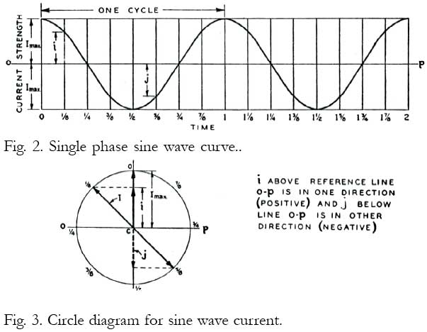
In Fig. 2 we have selected for zero time a moment when the current is positive and has its greatest value. Its instantaneous value at any other instant is now readily obtained by measuring the perpendicular distance from the line OP to the curve, at the chosen instant. Thus, at time “1/4" the current is changing direction and its value is zero. At time “3/8" the current is negative, and has somewhat less than its maximum value.
In the second method of representation, shown in Fig. 3, a circle is drawn which has a radius proportional in length to the maximum value which the current attains at any time. One radius of the circle, called a vector, as the line I, is then assumed to rotate in an anticlockwise direction around C, the center of the circle. It is taken to rotate at such a speed that the arrow end of this vector will travel once around the circumference of the circle in the time required for the alternating current to go through one complete cycle. When these assumptions are made, the value of the current at any particular moment may then be found by dropping a perpendicular from the arrow end of the rotating vector on any selected diameter of the circle. In Fig. 3 we have chosen the top end of the vertical diameter for our zero time. If the vector has turned anti-clockwise through one-eighth of a circumference, the value of the instantaneous current is then given by the distance i, along the vertical diameter of the circle. As this distance is measured above the horizontal diameter of the circle, the current is positive. When the vector has revolved five-eighths of the way around the circle the instantaneous value of the current is then given by the line j, and as this line lies below the horizontal diameter of the circle the current is flowing in a negative direction. Values of the alternating current obtained by this procedure, using Fig. 3, check with the values obtained by the use of Fig. 2.
Let it now be supposed that we have a single-layer coil of wire, wound, let us say, on a paper mailing tube; then when an alternating current is flowing in the coil there will be lines of magnetic force within the tube. These lines of force are uniformly distributed over the space within the tube, except near its very ends, and they are in a direction strictly parallel to the axis of the tube. When the current in the coil increases in value, the number of lines of magnetic force increases in the same proportion as the current, and decreases when the current decreases. If the current in the coil is flowing in the positive direction the lines of magnetic force are directed along the tube in a direction, say, from left to right; and when the current flows in the negative direction, the lines of force are oppositely directed. When the alternating current is passing through its zero value, there are no lines of force in the tube at that instant. In technical language, the flux (lines of force in the tube) is in phase with the current in the coil. We may represent, therefore, the rise and fall of the flux in the tube with diagrams precisely like the diagrams, Figs. 2 and 3, which represent the current, by merely substituting strength of magnetic field for strength of electric current.
If a loosely fitting hollow cylinder of metal — such as aluminum or stainless steel — is placed in the tube, then by a fundamental law discovered by the great Faraday in 1832, an electric current will be induced in the metal cylinder. This induced current will flow circumferentially around the metal cylinder, always in a direction substantially opposite to the current flowing in the coil winding. The induced current in the cylinder will be much larger than the current in the coil. If there are ten turns in a length of the coil equal to the length of the cylinder, then the amperes of current which flow in the cylinder will be a little less than ten times the amperes which flow in the coil winding.
Another fundamental law states that the current induced in the metal cylinder raises the temperature of the cylinder, and that this pse of temperature is proportional to the square of the induced current. Thus, if in a time of one minute a certain current heats the cylinder 10°, a current twice as large will heat it 40° in the same time.
But the fact which interests us here is that there is not the slightest tendency for the metal cylinder to move in either direction along the axis of the tube when a single-phase alternating current is flowing in the coil. To make an electric gun which will forcibly move a cylindrical metal projectile along the axis of a tubular coilwinding, we must resort to something other than a simple alternating single-phase current. This result may be achieved by making use of what is termed a polyphase current. “Polyphase current” is the general term for so-called two-phase, three-phase, six-phase, and higher-phase currents. As our results were accomplished with three-phase currents, I shall make no further reference to currents of other phases than three.
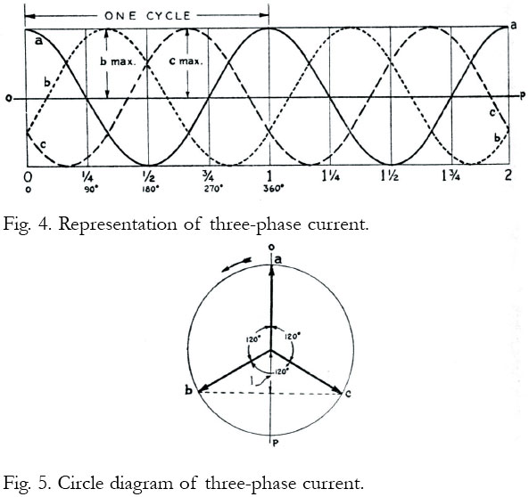
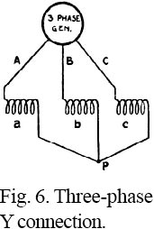
It will help to an understanding of three-phase currents and their properties to draw two more diagrams, Figs. 4 and 5, very similar to Figs. 2 and 3 used above in explanation of the nature and properties of single-phase alternating currents. There is also added, in Fig. 6, a diagram of three coils a, b, c, so connected that a three-phase current can flow through them.
 Three-phase currents are nothing more
than three single-phase
currents which reach their maximum value
at three different times. These currents are
carried from their source — usually an
electric generator with three sets of
windings — by three wires, as shown in Fig.
6. If the three currents are to be used to
supply three coils wound on a tube, one end
of each of these three coils may be joined at
a common point p. The other ends of the
coils are then connected to the three
conductors which lead from the source of the currents. We may
designate the currents flowing in the lead-wires A, B, C, by the
letters a, b, c respectively.
Three-phase currents are nothing more
than three single-phase
currents which reach their maximum value
at three different times. These currents are
carried from their source — usually an
electric generator with three sets of
windings — by three wires, as shown in Fig.
6. If the three currents are to be used to
supply three coils wound on a tube, one end
of each of these three coils may be joined at
a common point p. The other ends of the
coils are then connected to the three
conductors which lead from the source of the currents. We may
designate the currents flowing in the lead-wires A, B, C, by the
letters a, b, c respectively.
For the first method of representing the instantaneous values of these three currents at each instant of time, we draw the diagram Fig. 4. This diagram is exactly like the diagram Fig. 2 representing a single-phase current, except that in the same diagram in addition to the current a the currents b and c are also shown. The current curve for b is just like the current curve for a, except that the curve is shifted toward the right so that the first maximum of b occurs at a later time than the maximum of a, by an amount equal to one-third the time of a complete cycle. The maximum for current c in turn comes one-third later than for b. These three currents are said to differ in phase by 120°, because in the circle diagram (Fig. 5) the three vectors which represent the maximum values of currents a, b and c are drawn so that they make angles of 120° with one another.
The second or circle method of representation which Fig. 5 shows, is simple and very convenient for finding the instantaneous values of currents a, b, and c at any instant. Here the three vectors, always maintained at angles of 120° with one another, are assumed to rotate around the center of the circle at a uniform speed. Each vector makes a complete revolution in the time required for the current of any one phase to complete its cycle. In the case of a sixty cycle current this time would be one-sixtieth of a second. Again, if the frequency of the current is one thousand cycles per second, then the vectors a, b and c would make a thousand revolutions in a second, or one revolution in one thousandth of a second.
Just as in the case of a single-phase current, the instantaneous values of the currents a, b, and c at any selected instant may be found by dropping a perpendicular from the arrow end of a vector to the vertical diameter of the circle, and then measuring the distance from the end of this perpendicular to the center of the circle. For example, in the position of the three vectors as shown in Fig. 5, the instantaneous value of current a is a maximum; the instantaneous value of current b is represented by the distance l. In this particular case the instantaneous value of the current c is the same as that of b.
Three-phase current possesses a most important property which a single-phase current does not possess — a property whereby linear motions of extremely great velocity may be obtained. The important property is this: Fed into solenoidal coils wound in line on a long tube, the three-phase current develops what I shall term a “travelling wave of magnetic force.” The magnetic field in the first coil reaches its maximum value a little earlier than in the second coil; and in the second coil a little earlier than in the third coil. In other words, the crest of a wave of magnetic force moves forward along the axis of the line of coils. With proper choice of frequency of the current, the manner of connecting the coils, and their length and spacing, the wave-crest of magnetic force may be made to move through the coils from left to right, or from right to left — as the connections are made — at a terrific speed, far greater in fact than the speed of any projectile ever shot from a gun.
If a metallic body such as a hollow metal cylinder be placed within the tube on which the coils are wound, currents are induced in it by the rapidly changing magnetic field. These react with the currents in the coils in such manner that the metallic body is swept along through the tube as if blown by a powerful blast of air. If the tube is long, and wound with many coils, the body will continually gain speed; and if the tube is sufficiently long, the velocity of the moving body will continue to increase until it is going very nearly as fast as the crest of the travelling wave of magnetic force. Here is offered, in theory, a practical physical means of imparting a velocity to a material body, such as a hollow projectile, which will take it so far into space that the powerful pull of the earth’s gravity will not bring it back again.
The dimensions, in diameter and length, which can be given to a steel gun are extremely limited. The diameter and length of coils which constitute an electric gun are limited only by consideration of cost.
It is advisable to explain here a few further details regarding the type of winding, the number of coils employed, the method used in connecting coils, the length and diameter of a particular experimental gun, and the velocity theoretically obtainable by use of the travelling magnetic waves which move along its axis.
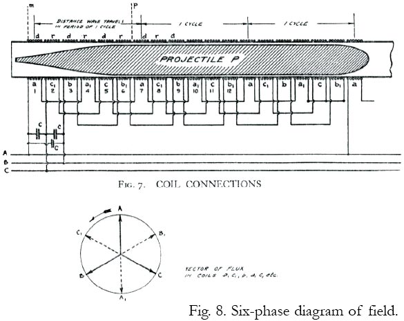
Calculations and experiments show that the best arrangement of coils and electrical circuits is that given in Fig. 7. In this diagram is drawn in section a portion of the length of a very long tube — the barrel of the electric gun. Inside the tube is shown — also in section— a hollow projectile P. This is streamlined at both ends. Outside the barrel are placed the coils. Each of these is made of tubing wound in a single layer. Tubing rather than solid copper wire is employed so that water may be passed through the coils to keep them cool when, for more than a few seconds, extremely large electric currents are used.
In the length of barrel between dotted lines m and p of Fig. 7, six separate coils are wound. The length of each individual coil may be advantageously chosen about equal to the radius of the barrel, and the distance between any two coils may be a fraction of the length of one coil. It is especially to be noted that if the first coil, a, is wound right-handedly, the next coil, c1, is wound left-handedly, and so on with alternate coils. Directly-wound and reversely-wound coils are designated in Fig. 7 by the letters d and r respectively. The first coil, a, is joined in series with the fourth coil, a1; the second in series with the fifth, c; and the third in series with the sixth, b1. The left-hand ends of the three coils are joined to the line wires. A, C, B, which go to the source of the supply — a large three-phase electric generator. The group of coils 7, 8, 9, 10, 11, 12 repeat in sequence and manner of connection the group which includes the first six coils, and so on for a gun of any length. With these connections there will be as many waves of magnetism as there are sets of six coils each. Thus, the length of the gun barrel may be extended indefinitely by simply increasing the number of sets of six coils each.
It should now be noted that while the currents in the conductors A, B, and C, which feed the coils, are 120° apart in phase, the magnetic flux in any set of six coils differs in phase from coil to coil by only 60°. This is made understandable by considering the circular vector diagram Fig. 8. Thus when A is taken as the vector of the flux which threads through coil a, C will be the vector of the flux which threads through the second coil lettered c1. Since this coil is wound reversely, and since the current which is fed into it from conductor C is 120° behind the current fed into the first coil, the flux—due to the fact that the winding is reversed — is only 60° behind the flux of the coil a. The phase of the flux in the coils which are wound left-handedly is shown in Fig. 8 by vectors drawn in dotted lines, and in coils which are wound right-handedly by vectors drawn in full line. The windings as above described make the crests of the magnetic waves progress in the gun barrel evenly and smoothly.
It is to be noted that in the case shown an electric condenser (conventionally represented) is joined across each phase of the supply conductors. These condensers, designated by the letter c in Fig. 7, perform a most important function, which I have fully considered in this technical supplement under a separate heading.
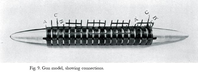
To further clarify the matters discussed above, a small wooden model of a projectile has been constructed and wound with copper coils in the most approved manner. A photograph of this model is reproduced here, and it is described further on page 310. The illustration will help to give a mental picture of how a polyphase high-frequency electric gun should be constructed.
| < Previous | Page 7 of 17 | Next > |
©1998-2026 Barry Hansen