Barry's Coilguns
AC Linear Induction Motor
- Introduction
- Experiment
- Line-Throwing Gun
- Thrust
- Thrust Constant
- Losses
- Traveling Waves
- Resistance
- Capacitors
- Series Parallel
- Energy Storage
- Power Shifting
- Projectile Heat
- Magnetic Field
- Impedance Drop
- About Northrup
- Preface
Power Shifting Device
Figure 11 illustrates one of several means by which any section of the electric gun can be energized without simultaneously energizing all of the gun coils. Contact terminals c1, c2, c3, . . . placed around the inside of the gun, when connected by the contact ring on the projectile to terminal c0, cause relays to close switching devices s1, s2, s3m . . .
These switching devices, for quick action, should be constructed on principles similar to thermionic vacuum tubes. As the projectile moves forward from left to right, switches connecting coils to the rear of the projectile are progressively opened, while switches connecting coils just ahead of the projectile are progressively closed. By having the right number of contact terminals, and by having them begin and end at the right places, any number of coils can be energized in exactly the right sequence, regardless of the speed of the projectile.
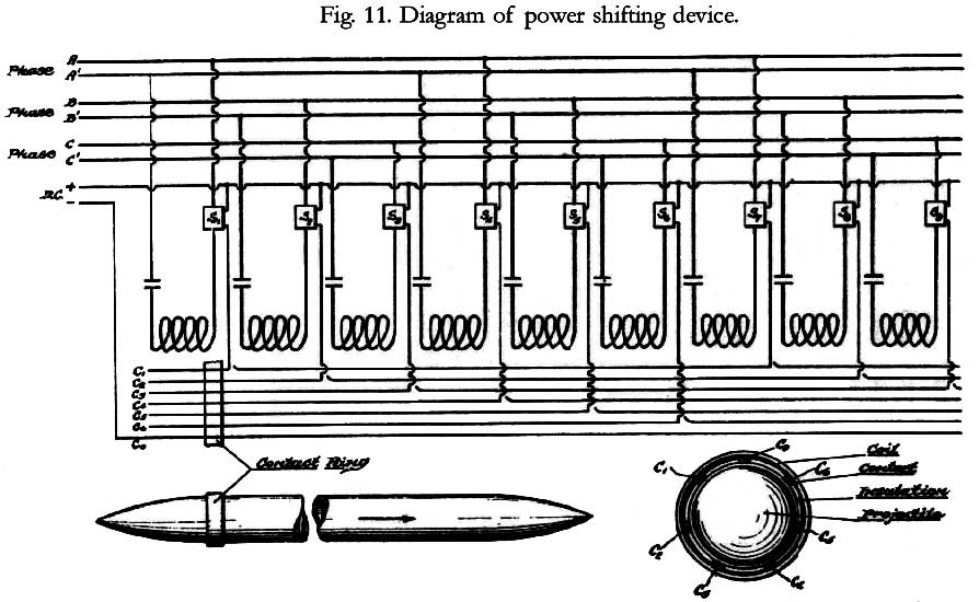
Fig. 11. Diagram of power shifting device
| < Previous | Page 12 of 17 | Next > |
©1998-2024 Barry Hansen