Barry's Coilguns
Mark 5
- Introduction
- Contactor
- Capacitors
- Bus Bar
- Control Panel
- Buying Parts
- Cart
- Spark Gap
Capacitor Bank Construction
How can you reform the dielectric insulator inside a used electrolytic capacitor? How can we safely discharge a 6KJ capacitor bank into a dummy load?
Capacitor Specifications
The capacitors are Philips part number 3186GH242T450AJA2 with this datasheet. The datasheet tells us to decode the part number thusly:
| 3186 | GH | 242 | T | 450 | A | J | A2 |
|---|---|---|---|---|---|---|---|
| | | | | | | | | | | | | | | | |
| Type | Case Code |
Capacitance 24 x 10^2 (2400 uF) |
Tolerance M = +/- 20% S = -10/+30% T = -10/+50% U = -10/+75% |
Volts | Post Type |
Insulation J = 0.012" PVC |
Construction |
Capacitor Bank
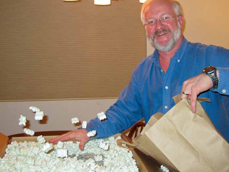
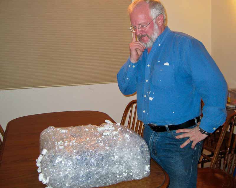
These caps were quite used and abused. I asked the eBay seller about their history, but he had no idea how old they were or what kind of equipment they came from. I really wonder if they meet specifications. I think they were dumped roughly in a giant bin, and then exquisitely well packed for shipment!
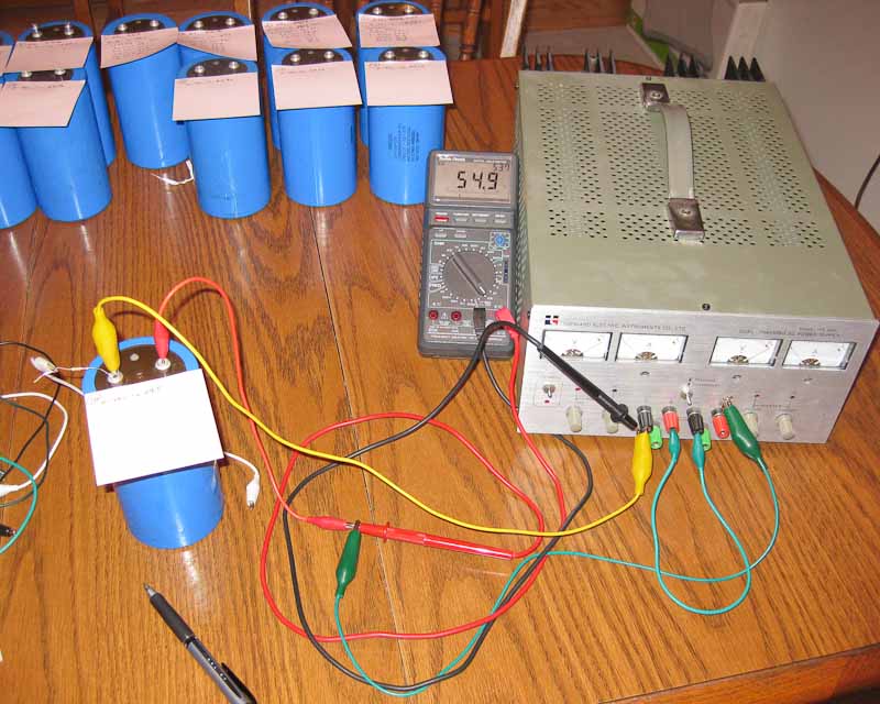
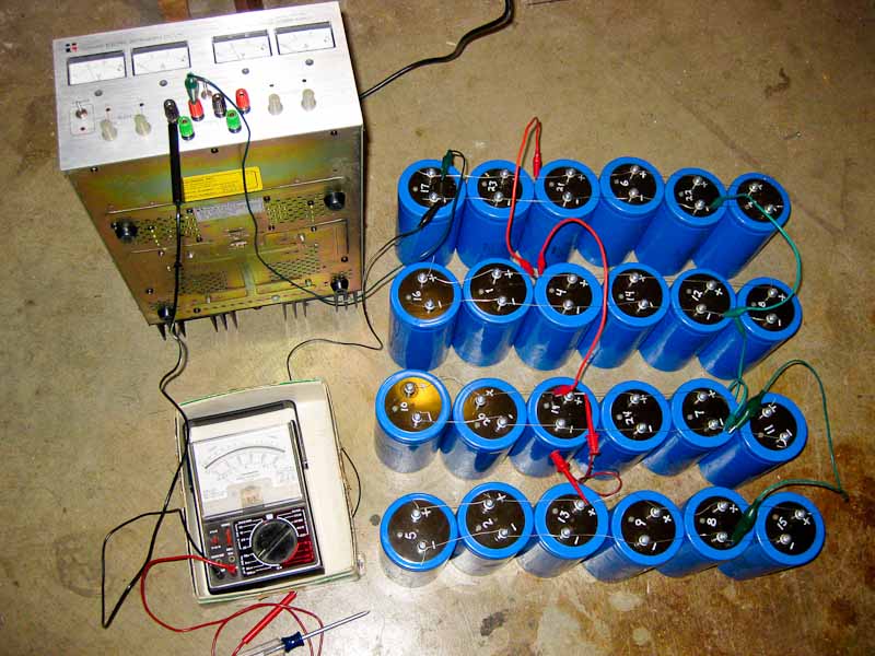
The first step is to measure capacitance and leakage current. I measured the RC time constant with a stop watch. This picture shows a 64v power supply, voltmeter and 10K series resistor. Remember the standard equation for capacitor voltage as a function of time: V = V0 * [1 - e^(-t/RC)]
Solve this for capacitance C. Then plug in any specific pair of corresponding voltage and time, and you have the value of capacitance: C = -t / [R * ln(1 - V/V0)]
For convenience I chose 40v for my time measurement point, and wrote a simple spreadsheet to keep track of capacitors. I used pink sticky notes to write measurements on each capacitor as they were taken. I reviewed the external condition and sorted the capacitors into groups according to how badly dented they were. Later, you'll see the capacitors numbered to match my spreadsheet.

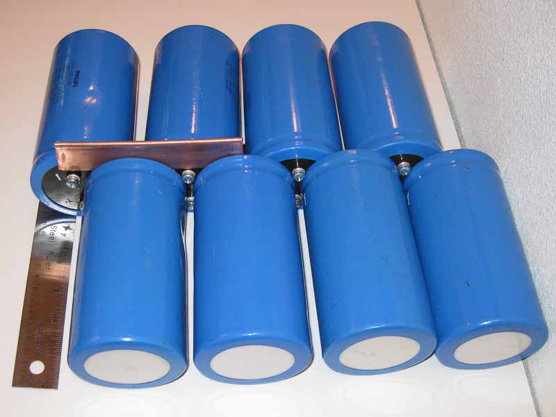
Some initial fiddling suggests that stacking capacitors in two rows with terminals facing each other will result in the shortest required busbar connections. Shorter busbars means lower resistance, so there we go. The picture shows a short piece of copper pipe hammer flat as a sample busbar; here it is loosely set in place for scale.
Reforming Capacitors
Reforming capacitors will improve performance and safety. By applying a gradually increasing voltage, the internal dielectric barrier will be restored through electrochemical action.
Reforming is done by applying a fixed voltage and waiting until current eventually drops to zero. The setup below shows how all 24 capacitors were temporarily connected in parallel and slowly charged.
The lab supply is good for 0 - 64vdc, and the ammeter monitored the charging current. I was relieved to find that leakage current was very low (under 0.1 mA) after it settled down. The bank would typically draw 1 - 5 mA for up to an hour at each new voltage, and finally drop to zero which indicates (we think) the aluminum oxide layer is completely reformed through chemical action.

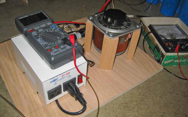
For higher voltages I built a cheap adjustable power supply from (1) a cheap chinese 1:2 transformer rated 500 VA, (2) a Variac rated for 6A and (3) a diode bridge rated for 10A at 400v.
This can be dangerous! If a capacitor breaks down it can draw a great deal of current from this supply and soon explode. I placed the whole assembly away from people (in the garage) and monitored the charging current frequently.
Safe Discharge
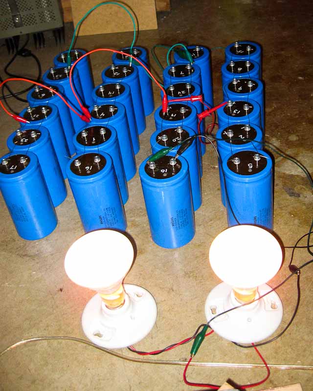
Okay, now I've got 2KJ of stored energy. Now what? I need to safely discharge this somehow. At first I tried a 25-ohm 50-watt resistor. Bad idea. When my eyes recovered from the flash, I tried a 100-ohm 50-watt resistor. At least the flash was smaller and the sparks were only 1" long. But still not a good way to dump energy.
To safely discharge 2 kilojoules at 380vdc, it turns out that two 64-watt light bulbs connected in series will provide an excellent load. Light bulbs have the nice characteristics of a steady current sink. They offer high resistance at high power, and low resistance at low power, thereby draining the capacitor bank much more quickly than a simple RC time constant.
| < Previous | Page 3 of 8 | Next > |
©1998-2024 Barry Hansen