Magnetic Levitation
Levitation from LNS Technologies
Theory of Operation
The kit's manual has a useful description of how the levitator works. It is reprinted below by permission of the author.
Overview
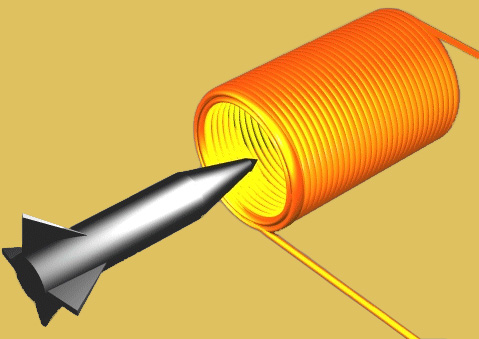
The levitator uses an electromagnet to create a magnetic field which attracts a hollow steel globe or similar object upward.
An infrared emitter and detector are mounted across from each other to create an invisible beam which passes slightly below the coil. As the object rises toward the electromagnet, it starts to block the beam. When the beam becomes blocked, the output of the detector is reduced which in turn reduces the current in the coil. The reduced current weakens the magnetic field, the object begins to drop and the detector once again sees more of the beam. This causes the circuit to increase the magnetic field and the cycle repeats as the object is attracted upwards again.
The circuit is designed so that eventually an equilibrium is reached where the magnetic attraction exactly balances the force of gravity pulling on the object. The object then remains perfectly suspended in the infrared beam's path with no visible means of support!
Circuit Description
Power supply: Refer to the schematic of the levitator shown in Figure 1. Power is supplied by a 12-volt DC, 1000 mA wall -mounted power pack. In our original levitator design, if the transformer wires were accidentally reversed, the LM78L09 regulator was destroyed. This new design uses a diode bridge (DB1) to protect the U2 regulator. DB1 delivers the proper DC polarity to U2 no matter how the transformer wires are attached.
Coil power: The coil uses most of the current in this circuit, so it is powered directly from the 12V output of DB1. Stable voltage for the rest of the circuit is obtained by regulating the 12V down to 9V with U2, a LM78L09 voltage regulator IC. Capacitors C1 and C3 provide additional voltage filtering. U2 is capable of supplying up to 100 mA of current.
Infrared emitter: IRLED is an infrared LED (Light Emitting Diode) like the ones used in television and stereo remote controls. Resistor R15 limits the forward current to IRLED at around 15 mA. IRLED emits a constant invisible beam whenever power is ON. IRDET is an infrared photo transistor detector that is wired with R6 and VR1 to convert the infrared beam into a DC voltage. The potentiometer VR1 adjusts the IRDET voltage level into pin-5 of U1.
Amplifier: The voltage signal from IRDET is buffered and amplified by the operational amplifier U1B. U1B is half of an LM358N with a gain of 2 [(R11+R10)/R11]. The output of U1B is fed to a second amplifier stage, (U1A) through C3 and R12. The output signal from U1A drives transistor Q5 to vary the current to the electromagnetic coil. Q5 gets very warm during operation and requires a good heat sink. Diode D1 protects Q5 from reverse voltage spikes.
Differentiator: The mylar capacitor C4 plays an important role in this circuit. C4 forms a differentiator with U1A. This capacitor blocks slow voltage changes, but passes any rapid changes in the input signal and allows them to be amplified by U1A. The slow voltage changes are attenuated by R12 and R7 before being amplified by U1A. The purpose of this part of the circuit is to perform closed-loop control using a combination of proportional and derivative modes. Both modes are needed to insure that the levitation system is stable. The theory of continuous closed-loop control involves more than can be explained here, so some readers may want to do further study on their own.
Overheating protection: With nothing blocking the IR beam, the output of U1B will be greater than 2.7 volts. This causes Q4 and Q3 to turn ON, which turns Q2 and Q1 OFF and the coil receives no current. Likewise, if the beam is completely blocked, the output of U1B will drop below 0.7 volts. Again Q4 and Q3 will be ON which forces Q2 and Q1 OFF. However, when the object is partially blocking the beam during levitation, the voltage out of U1B should be somewhere between the 0.7 and 2.7 volt thresholds. Now Q4 and Q3 will be OFF, with Q2 and Q1 ON. Whenever Q1 is ON, the red LED indicates that Q5 and the COIL are receiving current.
| < Previous | Page 3 of 5 | Next > |
©1998-2024 Barry Hansen