Barry's Coilguns
Mark 4
- Introduction
- Objectives
- Schematic
- Projectiles
- Capacitor
- Kinetic Energy
- Timing
- Coil Design
- SCR
- Diode
- Damping Resis
- Bleeder Resis
- Iron Type
- Iron Shape
- Iron Size
- Low Voltage
- High Voltage
- Isolation
- Low Voltage Power
- Charging Resis
- Construction
- Firing Tube
- Retention Bolt
- SCR Wiring
- Transformer
- External Iron
- Purchases
- Speed Measurement
- Results
- Coil of 97 Turns
- Coil of 84 Turns
- Damping Resistor
- Burned Coil #1
- Coil of 56 Turns
- Eddy Currents
- Starting Position
- Conclusions
Coil of 84 Turns
This was the second coil tested, smaller than the first coil tested by 13 turns.
Coil of 84 Turns
See the Projectiles page for details of these projectiles.
MeasurementsThe raw measurements are shown in red in the table below, using horizontal ballistics measurements. The symbol "-" indicates that it was not attempted, and "dnf" means "did not fire". |
|||||||
Projectile: |
A |
C |
D |
E |
F |
G |
|
|---|---|---|---|---|---|---|---|
| Length: | 3.5" | 2.5" | 2" | 1.75" | 1.5" | 1.25" | |
| Mass: | 4.301 g | 2.163 g | 1.464 g | 0.8722 g | 0.7345 g | 0.4421 g | |
Potential energy (joules) |
Charge (volts) |
Horiz
Distance (inches) |
Horiz
Distance (inches) |
Horiz
Distance (inches) |
Horiz
Distance (inches) |
Horiz
Distance (inches) |
Horiz
Distance (inches) |
| 0.6 J | 10 v | dnf | - | - | - | - | - |
| 2.4 | 20 | 40 | - | - | - | - | - |
| 5.4 | 30 | 69 | - | - | - | - | - |
| 9.6 | 40 | 96 | - | - | - | - | - |
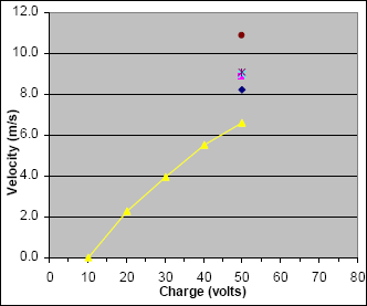
| 15.0 | 50 | 115 | 144 | 155 | 157 | 159 | 190 |
VelocityAgain using the equations for horizontal ballistics and the raw data, the velocity is calculated for each of the measurements above and is shown in red. |
|||||||
Projectile: |
A |
C |
D |
E |
F |
G |
|
Potential energy (joules) |
Charge (volts) |
Velocity (m/s) |
Velocity (m/s) |
Velocity (m/s) |
Velocity (m/s) |
Velocity (m/s) |
Velocity (m/s) |
| 0.6 J | 10 v | 0.0 | - | - | - | - | - |
| 2.4 | 20 | 2.289 | - | - | - | - | - |
5.4 |
30 | 3.949 | - | - | - | - | - |
| 9.6 | 40 | 5.494 | - | - | - | - | - |
| 15.0 | 50 | 6.581 | 8.241 | 8.871 | 8.985 | 9.100 | 10.874 |
EfficiencyCalculate efficiency as shown in red. |
|||||||
Projectile: |
A |
C |
D |
E |
F |
G |
|
Potential energy (joules) |
Charge (volts) |
Efficiency (%) |
Efficiency (%) |
Efficiency (%) |
Efficiency (%) |
Efficiency (%) |
Efficiency (%) |
| 0.6 J | 10 v | 0.0 % | - | - | - | - | - |
| 2.4 | 20 | 0.5 | - | - | - | - | - |
| 5.4 | 30 | 0.6 | - | - | - | - | - |
| 9.6 | 40 | 0.7 | - | - | - | - | - |
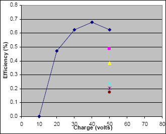
| 15.0 | 50 | 0.6 | 0.5 | 0.4 | 0.2 | 0.2 | 0.2 |
Graphical Results
Coil Analysis
This coil with 84 turns measured 6 ms half-cycle waveform (an oscilloscope image is not available).
The 6 ms timing is a good result compared to predictions from using the approximate air-core inductor model. This confirms our approach (applying a percentage change from air-core inductance to an iron-core model) is useful.
How Does This Coil Need to Change?
The speeds and efficiencies are still very low. We wish to reduce the time from 6 ms by 33%, to reach 4 ms discharge time.
We will again apply a percentage change from an air-core approximation to our iron-core physical coil.
- Using the Java Inductor Simulator again with values of 12 AWG, ID=6mm, OD=60mm, len=16mm, we find that our inductance would be L = 118 uH for an air-core coil.
- We want a 1/3 smaller LC time constant (i.e. 6 ms becomes 4 ms)
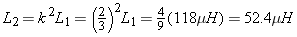
- The new coil in air should therefore have L = 52.4 uH
- The Java Inductor Sim suggests a 70 turn coil will have the desired inductance.
- Therefore, removing 14 turns should result in a 4 ms discharge time.
Damping Resistor
Note the damping resistor will likely need to be changed. As the LC time constant becomes smaller, the resistor also should be reduced to remain at the critically-damped point. Without any resistor change, the tuned circuit will be over-damped and the waveform is lower and longer than desired.
We also found an unexpected and fascinating behavior of this resistor's construction, which required a slight redesign as described in the next page about damping resistor construction.
| < Previous | Page 31 of 37 | Next > |
©1998-2024 Barry Hansen