Magnetic Levitation
Visual Levitation
Visual Levitation Implementation
As an electronics hobbyist I love to see how things are built. Having designed my own levitator, I am always interested in improvements and may yet build my own new and improved model. (I know my toy is pretty lame!) This page has notes and comments about how the Visual Levitation device was built.
Lifting Coil
The lifting coil measures between 19 and 20 ohms of resistance. It appears to be a single coil of 28 AWG magnet wire (not double strand or litz wire).
So assuming no reactance/inductance we know the current draw in the coil is no more than 632ma max probably closer to 600ma and we can probably assume some loss in the H-bridge. I kind of figured his coil would draw more current at max, but I guess since it was optimized to run with the magnets doing all the work not the coils, it makes sense.
Coil Dimensions
The coil assembly is approximately 63 mm in diameter and 87 mm tall. It provides 24 mm of flying height with the current adjustment. More detail is shown when you click on these photos.
coil diameter |
coil height |
flying height |
 |
 |
 |
63 mm |
87 mm |
~24 mm |
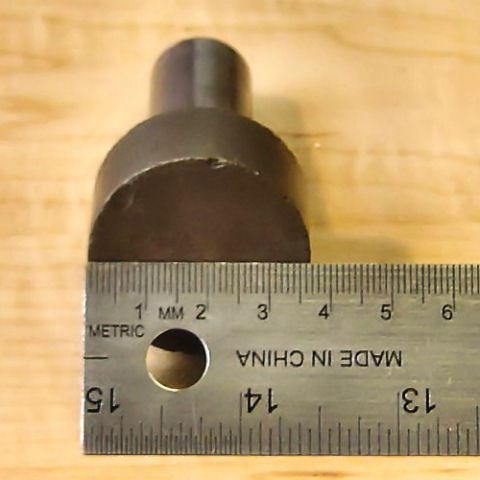
Iron Core
There is a plain 3/4" cylinder of iron core. As far as I can tell, it is ordinary iron stock. Although the good Dr. seems to have thought of everything, I don't see any attempt to reduce eddy currents. Perhaps it could be improved with this in mind. Typically it means cutting a slot down the side of the core, or using laminations such as say ten 16-penny nails with the ends cut off. Or maybe he did think of it, and eddy currents are negligible in this application (I doubt it).
Flux Concentrator
The patent describes a mu-metal flux concentrator on top of the coil, in a top hat arrangement. However, the commercial levitator does not include it.
I would expect the flux concentrator makes no significant difference. There would still be a few inches of free space from this pole to the object, which would dominate the total magnetic reluctance in the flux path.
Hall Effect Sensors
The patent suggests using two Hall-effect sensors under the lifting coil for increased sensitivity. The x-ray images apparently show two sensors, but it is difficult to make out.
Certainly all the sensors are at the bottom of the lifting coil. There is obviously no sensor at the top of the coil assembly.
I've seen no evidence of magnetic shielding around the sensors. The x-ray image does not show anything obvious. Since there is none at the top, I will assume it is not at the bottom, either.
I wonder if it has problems with sensor saturation. The best device I've found looks like it saturates at about .16 Tesla. This is achievable with very strong magnets. However, the levitator works so well that either it has a sensor with a high dynamic range, or it mainly operates at lower levels.
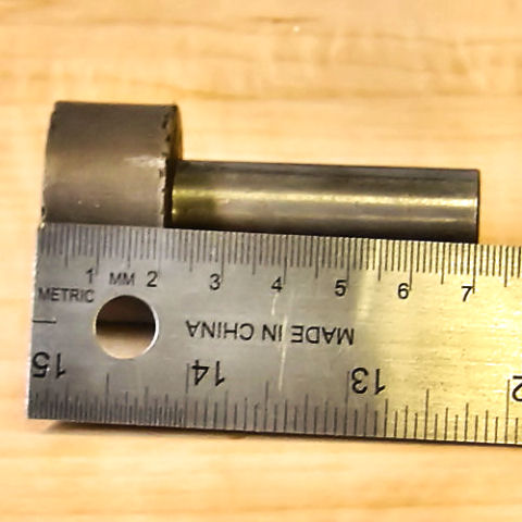
Mondo Magnet
The magnet and calibration rod are shown below.
magnet diameter |
magnet height |
rod diameter |
 |
 |
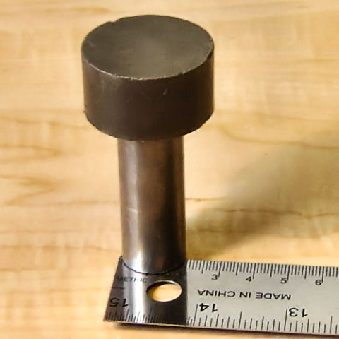 |
36.5 mm |
20 mm |
19 mm |
Still checking to see if the unit uses a Neodymium Magnet, or one of the older Samarium types. Due to the fact Neodymium is more powerful than Samarium, you could possibly use a smaller magnet with the same lifting capability.
The NdFeB is the Neodymium super magnets.
Power Fail Feature
In case of power failure, this levitator will park the object under the lifting coil. This is inherent to the operating point; the object is normally just above the magnetic balance point and the coil is normally pushing it downward. When power is lost, the result is that it jumps upward.
A more sophisticated version of this levitator (not the kit) is sold for corporate displays and museums, and it will automatically re-launch the object when power is restored.
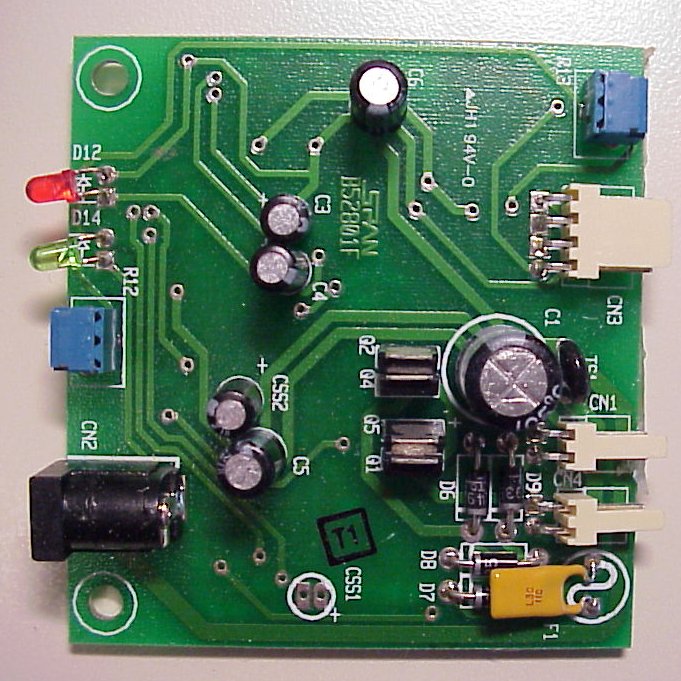
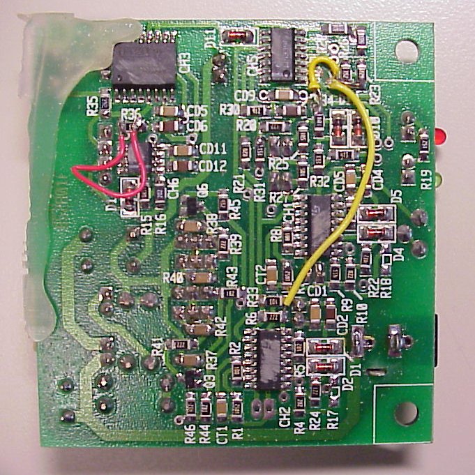
Printed Circuit Board
The control electronics are neatly manufactured with both feed-through and surface-mount components. Here are photographs of both sides.
| top view | bottom view |
 |
 |
Power Supply
The power pack on my VisLev kit is rated at 12vdc and 1A. Since it never gets warm, I assume the kit is drawing much less than that.
- It was convenient of them (for me!) to run two small cables from the controller to the lifting head.
- The two-wire cable must be the lifting coil, and it connects to the PCB adjacent to four small power transistors, on the connector labeled CN1.
- Interesting to notice there is another identical connector labeled CN4 which is unused, but it fits the coil connector.
- The four-wire cable must be the sensors, and it connects adjacent to the Burr-Brown 16-pin chip.
PWM Frequency
The coil is driven by a PWM frequency of 29us or ~34.5kHz.
A friend found a potentialy useful H-bridge (Allegro 3959 or 3952), it has an adjustable PWM frequency, unlike the LMD18201. Frequency is the problem, too much inductance at high frequencies and it will draw too much current from the H-bridge, and at low frequency the coil gets hot. Need to find the happy medium.
Ring Magnet Suspension
So I read through patent application 20040052029, and one interesting thing is the "ring magnet" suspension. Of course this device doesn't use one (it is a follow-on patent) but a broad diffuse suspension seems counter to what I figured out. I still believe a good levitator needs a point source lifting from above, such as from a tapered iron core. This provides the lateral pull to return the object back to the middle of the lifting axis.
| < Previous | Page 7 of 7 | Next > |
©1998-2026 Barry Hansen